-
32单片机基础:GPIO输入
1.1按键控制LED
按键介绍:


两种方式,我们一般用下接的方式。
第一个图:注意点。当按键按下,PA0接地,被置为低电平, 但是一旦按键松手,PA0悬空,引脚电压不确定。所以无论怎么读引脚也不知道知否被按下,所以为了解决这个问题,所以必须要求PA0是上拉输入的模式,这样引脚悬空的话,就会被置为高电平,这样我们我们就可以读取PA0的电压就知道按键是否被按下。
但是第二个图就不会出现问题,按下时,被置为低电平,松手,由于上拉电阻的作用,被置为高电平。这样引脚就不会出现浮空状态。所以此时PA0可以配置浮空输入和上拉输入。上拉输入,两个电阻共同作用,这样高电平就会更加稳定一些,
第三个图同样注意要使用下拉输入模式。
下面是面包板接线图:

用哪个端口看自己的,我这里也没按上面连接,我是接A0,A1两个端口
采用模块化编程:
把LED的代码和按键的代码封装开来,不要一起放在主函数里。分别放在自己的.c和.h文件里。
新建一个文件夹,用来存放硬件驱动


点击keil5的魔术棒:

把文件夹添加进来之后,像建立main函数一样建立下图文件。

LED.h用来存放这个驱动程序可以对外提供的函数或变量声明。
按照Ctrl+Alt+空格,会弹出相应函数的提示框。
LED.c
- #include "stm32f10x.h" // Device header
- void LED_Init(void)//打开时钟,配置端口
- {
- RCC_APB2PeriphClockCmd(RCC_APB2Periph_GPIOA,ENABLE);
- GPIO_InitTypeDef GPIO_InitStructure;
- GPIO_InitStructure.GPIO_Mode=GPIO_Mode_Out_PP;
- GPIO_InitStructure.GPIO_Pin=GPIO_Pin_0|GPIO_Pin_1;
- GPIO_InitStructure.GPIO_Speed=GPIO_Speed_50MHz;
- GPIO_Init(GPIOA,&GPIO_InitStructure);
- }
LED.h
- #ifndef __LED_H_
- #define __LED_H_
- void LED_Init(void);//打开时钟,配置端口
- #endif
main.c
- #include "stm32f10x.h"
- #include "Delay.h"
- #include "LED.h"
- int main()
- {
- LED_Init();
- while(1)
- {
- }
- }
这是,就会观察两个LED灯亮起来了,为啥我们没有配置高低电平,他会亮呢,因为我们的电路是低电平点亮,GPIO配置好了之后默认是低电平。
可以在初始化后面加GPIO_SetBits(GPIOA,GPIO_Pin_0|GPIO_Pin_1);让LED熄灭。
GPIO_pin_0|GPIO_pin_1(×)p小写了
GPIO_Pin_0|GPIO_Pin_1(√)
后面我们配置好LED开的函数,灭的函数。
LED.c
- void LED_Init(void)//打开时钟,配置端口
- {
- RCC_APB2PeriphClockCmd(RCC_APB2Periph_GPIOA,ENABLE);
- GPIO_InitTypeDef GPIO_InitStructure;
- GPIO_InitStructure.GPIO_Mode=GPIO_Mode_Out_PP;
- GPIO_InitStructure.GPIO_Pin=GPIO_Pin_0|GPIO_Pin_1;
- GPIO_InitStructure.GPIO_Speed=GPIO_Speed_50MHz;
- GPIO_Init(GPIOA,&GPIO_InitStructure);
- GPIO_SetBits(GPIOA,GPIO_Pin_0|GPIO_Pin_1);
- }
- void LED0_ON(void)
- {
- GPIO_ResetBits(GPIOA,GPIO_Pin_0);
- }
- void LED0_OFF(void)
- {
- GPIO_SetBits(GPIOA,GPIO_Pin_0);
- }
- void LED1_ON(void)
- {
- GPIO_ResetBits(GPIOA,GPIO_Pin_1);
- }
- void LED1_OFF(void)
- {
- GPIO_SetBits(GPIOA,GPIO_Pin_1);
- }
LED.h
- #ifndef __LED_H_
- #define __LED_H_
- void LED_Init(void);//打开时钟,配置端口
- void LED0_ON(void);
- void LED0_OFF(void);
- void LED1_ON(void);
- void LED1_OFF(void);
- #endif
同理按上述方法,建立Key.c和Key.h

GPIO读取的四个函数:(按键需要读取I/O端口)
GPIO_ReadInputDataBit:这个函数是用来读取输入数据寄存器某一个端口的输入值的。
参数是 GPIOx,GPIO_Pin用来指定某一个端口,返回值是uint8_t,代表高低电平
GPIO_ReadInputData:这个函数比上一个函数少了一个Bit,它是用来读取整个输入数据寄存器的,参数只有一个GPIOx,用来指定外设。返回值是uint16_t,是一个16位数据,每一位代表一个端口值,
GPIO_ReadOutputDataBit:这个函数是用来读取输出数据寄存器的某一位,所以原则来说,它并不是用来读取端口的输入数据的。这个函数一般用于输出模式下,用来看一下自己输出的是什么。
下面LED的翻转就用了这个。
GPIO_ReadOutputData:这个函数也是少了一个Bit,意思也一样,是用来读取整个输出寄存器的。


这就是四个函数的用途:
Key.c
- #include "stm32f10x.h" // Device header
- #include "Delay.h"
- void Key_Init(void)//按键初始化,初始化为上拉输入模式
- {
- RCC_APB2PeriphClockCmd(RCC_APB2Periph_GPIOB,ENABLE);//我们按键接到GPIOB上
- GPIO_InitTypeDef GPIO_InitStructure;
- GPIO_InitStructure.GPIO_Mode=GPIO_Mode_IPU;//上拉输入
- GPIO_InitStructure.GPIO_Pin=GPIO_Pin_1|GPIO_Pin_11;
- GPIO_InitStructure.GPIO_Speed=GPIO_Speed_50MHz;
- GPIO_Init(GPIOB,&GPIO_InitStructure);
- }
- uint8_t Key_GetNum(void)
- {
- uint8_t Keynum=0;
- //读取GPIO端口
- if(GPIO_ReadInputDataBit(GPIOB,GPIO_Pin_1)==0)//表示按键按下
- {
- Delay_ms(20);//消抖
- while(GPIO_ReadInputDataBit(GPIOB,GPIO_Pin_1)==0);//直到松手
- Delay_ms(20);//消抖
- Keynum=1;
- }
- if(GPIO_ReadInputDataBit(GPIOB,GPIO_Pin_11)==0)//表示按键按下
- {
- Delay_ms(20);//消抖
- while(GPIO_ReadInputDataBit(GPIOB,GPIO_Pin_11)==0);//直到松手
- Delay_ms(20);//消抖
- Keynum=2;
- }
- return Keynum;
- }
Key.h
- #ifndef __LED_H_
- #define __LED_H_
- void Key_Init(void);
- uint8_t Key_GetNum(void);
- #endif
main.c
- #include "stm32f10x.h"
- #include "Delay.h"
- #include "LED.h"
- #include "Key.h"
- uint8_t KeyNum;
- int main()
- {
- LED_Init();
- Key_Init();
- while(1)
- {
- // LED0_ON();
- // LED1_OFF();
- // Delay_ms(500);
- // LED1_ON();
- // LED0_OFF();
- // Delay_ms(500);
- KeyNum=Key_GetNum();
- if(KeyNum==1)
- {
- LED0_turn();
- }
- if(KeyNum==2)
- {
- LED1_turn();
- }
- }
- }
当然,还有Delay函数没有拿进来,自己可以写一个Delay函数,自己写代码时可以加一些注释,方便自己和他人理解,注释的规范可以参考32库函数里面的
这就是按键控制LED点亮的全部过程了。
1.2光敏传感器控制蜂鸣器
光敏电阻介绍:

因为电阻变化不容易直接观察,所以我们将传感器元件通常与定值电阻进行串联分压,
接地电容就是滤波用的。 滤除一些干扰,保证输出电压波形平滑

AO得到的是模拟电压,要想得到数字电压,要对AO进行二值化的输出,,二值化是通过芯片LM393来完成的,LM393是一个电压比较器芯片。看下图所示。电容对VCC滤波。
电压比较器就是一个运算放大器。运算放大器当做比较器的情况如下,


 左边的是电源指示灯,通道电就亮,
右边是DO输出指示灯,它可以指示DO的输出电平。低电平点亮,高电平熄灭。
上拉电阻R5是为了保证默认输出为高电平的。

 电路连接图:

上电时,可以看到两个灯都亮了,当我们遮住光线,输出指示灯灭,代表输出高电平(DO),松手时,输出指示灯1灭,代表输出低电平(DO),电位器可以调节高低电平的判断阈值。
Buzzer.c(蜂鸣器模块)
- #include "stm32f10x.h" // Device header
- void Buzzer_Init(void)//打开时钟,配置端口
- {
- RCC_APB2PeriphClockCmd(RCC_APB2Periph_GPIOB,ENABLE);
- GPIO_InitTypeDef GPIO_InitStructure;
- GPIO_InitStructure.GPIO_Mode=GPIO_Mode_Out_PP;
- GPIO_InitStructure.GPIO_Pin=GPIO_Pin_12;
- GPIO_InitStructure.GPIO_Speed=GPIO_Speed_50MHz;
- GPIO_Init(GPIOB,&GPIO_InitStructure);
- GPIO_SetBits(GPIOB,GPIO_Pin_0|GPIO_Pin_12);
- }
- void Buzzer_ON(void)
- {
- GPIO_ResetBits(GPIOB,GPIO_Pin_12);
- }
- void Buzzer_OFF(void)
- {
- GPIO_SetBits(GPIOB,GPIO_Pin_12);
- }
- void Buzzer_turn(void)
- {
- if(GPIO_ReadOutputDataBit(GPIOB,GPIO_Pin_12)==0)
- {
- GPIO_SetBits(GPIOB,GPIO_Pin_12);
- }
- else
- {
- GPIO_ResetBits(GPIOB,GPIO_Pin_12);
- }
- }
Buzzer.h
- #ifndef __BUZZER_H_
- #define __BUZZER_H_
- void Buzzer_Init(void);
- void Buzzer_ON(void);
- void Buzzer_OFF(void);
- void Buzzer_turn(void);
- #endif
LightSensor.c(光敏传感器模块)
- #include "stm32f10x.h" // Device header
- #include "stm32f10x.h" // Device header
- #include "Delay.h"
- void LightSensor_Init(void)//按键初始化,初始化为上拉输入模式
- {
- RCC_APB2PeriphClockCmd(RCC_APB2Periph_GPIOB,ENABLE);//我们按键接到GPIOB上
- GPIO_InitTypeDef GPIO_InitStructure;
- GPIO_InitStructure.GPIO_Mode=GPIO_Mode_IPU;//上拉输入
- GPIO_InitStructure.GPIO_Pin=GPIO_Pin_13;
- GPIO_InitStructure.GPIO_Speed=GPIO_Speed_50MHz;
- GPIO_Init(GPIOB,&GPIO_InitStructure);
- }
- uint8_t LightSensor_Get(void)//得到DO的返回值,暗是1
- {
- return GPIO_ReadInputDataBit(GPIOB,GPIO_Pin_13);
- }
LightSensor.h
- #ifndef __LightSensor_H_
- #define __LightSensor_H_
- void LightSensor_Init(void);
- uint8_t LightSensor_Get(void);
- #endif
main.c
- #include "stm32f10x.h"
- #include "Delay.h"
- #include "Buzzer.h"
- #include "LightSensor.h"
- int main()
- {
- Buzzer_Init();
- LightSensor_Init();
- while(1)
- {
- if( LightSensor_Get()==1)//光线比较暗的情况
- {
- Buzzer_ON();
- }
- else
- {
- Buzzer_OFF();
- }
- }
- }
32单片机的C语言(与51些许不同)
数据类型


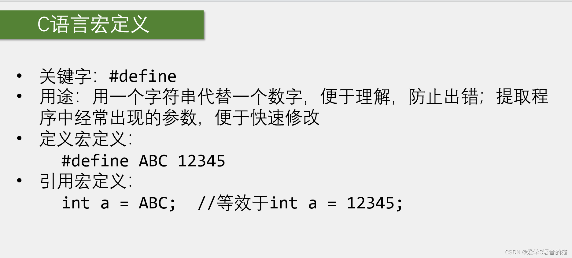
在库函数用了许多。下面是例子,
 只是这些不好理解,我们都换了一个让我们看得懂的名字。
 与上面有什么区别呢,宏定义任何名字都可以换,而typedef只能给变量类型换名字。所以宏定义的改名字范围要宽一些。
 这些没学好的再去学一下C语言吧。

-
相关阅读:
centos7 arm服务器编译安装onnxruntime-gpu
如何优化数据采集流程,让企业运营效率与竞争力飙升
Springboot登录验证的统一拦截处理
vCenter VXR01405C ALARM Certificate is about to expire
pygame 中的transform模块
第十四届蓝桥杯模拟赛第一期试题【Java解析】
pyppeteer框架基本语法备忘录
【第三章】神经网络的架构-前馈神经网络
实验1 Python程序设计基础
leetcode 刷题 log day 44
- 原文地址:https://blog.csdn.net/weixin_64484421/article/details/136200996
