-
F28069的cpu定时器
工程搭建参考:https://blog.csdn.net/feisy/article/details/126380289
F28069有三个32位的CPU定时器:0,1,2。0,1可用,如果程序未使用DIS/BIOS,定时器2也可用。


CPU定时器相关的有5个信号,四个输入信号,一个输出信号
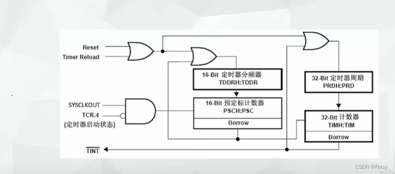
- Reset信号:复位信号,给定时器复位用的
- Timer reload:定时器重载信号,控制定时器要不要重新装载周期计算器
- SYSCLKOUT:系统时钟信号
- TCR.4=TCR.bit.4.TSS:控制定时器计时开始或者停止
- TINT:输出信息,周期中断

CPU定时器涉及的寄存器
- TDDR :定时器减一的时间长度,两个16位的寄存器表示
- PRD:设置CPU定时器的周期,两个16位的寄存器表示
- PSC开始计数时,会将TDDR 装载到这里,用来不断自减减到0,到0会产生TIMCLK信号,让TIM减一
- TIM:开始计数时,会将PRD 装载到这里,用来不断自减,,会产生一个中断信号,这时会回调定时器中断函数
- TPR:F28069里跟TDDR功能一样的寄存器?
- TCR:装载,启用或者停止定时器的寄存器:TCR.bit.TSS = 1(1 = Stop timer, 0 = Start/Restart Timer),TCR.bit.TRB = 1( 1 = reload timer),TCR.bit.TIE = 1( 0 = Disable/ 1 = Enable Timer Interrupt)

定时器的寄存器的形式是XH:X这样的形式,后半部分X表示低位,前半部分XH表示高位
#CPU定时器的工作原理

-
给CPU周期寄存器赋值

-
开始计数时,CPU会将计数值装在到TIM寄存器

-
每个一个TIMCLK,TIM会不断减一,一直减到0

-
减到0,完成一个定时周期,会产生一个中断
.
TIMCLK代表是了计数器减一的时间长度,它是通过定时器 的分频寄存器TDDR来设置的

计数时,TIMCLK会被装载到PSC寄存器

PSC里面的数值在每个SYSCLK都会减一,减到0时,会产生一个让TIMCLK减一的信号
一个计算例子
PDR会被装载到PSC,每个SYSCLK都会减一,减到0时,会产生一个让TIMCLK减一的信号,TIMCLK=(1+PDR)个SYSCLKOUT,以F28335为例,主频是150M,TIMCLK=(1+PDR)*(1/150M)秒一个周期是 (1+PRD) * TIMCLK

代码演示,通过定时器来控制LED闪烁
1 设置定时器的回调函数
注意,TINT0是在PIE TABLE的第7位,后面还有关于启用第一组,以及启用第7个中断的设置
// Interrupts that are used in this example are re-mapped to // ISR functions found within this file. EALLOW; // This is needed to write to EALLOW protected registers PieVectTable.TINT0 = &cpu_timer0_isr; EDIS; // This is needed to disable write to EALLOW protected registers- 1
- 2
- 3
- 4
- 5
- 6
- 7

2 获取定时器寄存器, 配置定时器的一些默认值
使用到的一个函数
void InitCpuTimers(void) { // CPU Timer 0 // Initialize address pointers to respective timer registers: CpuTimer0.RegsAddr = &CpuTimer0Regs; // Initialize timer period to maximum: CpuTimer0Regs.PRD.all = 0xFFFFFFFF;//PRD寄存器设置CPU定时器的周期,两个16位的寄存器表示,这里设置到最大 //TPR寄存器的作用是CPU会在(TPR[TDDRH:TDDR]+1)个SYSCLOUT后,将TIM减一,这里置0,表示,每个SYSCLKOUT都会让TIM减一 // Initialize pre-scale counter to divide by 1 (SYSCLKOUT): //The 32-bit counter register TIMH:TIM is loaded with //the value in the period register PRDH:PRD. The counter decrements once every (TPR[TDDRH:TDDR]+1)SYSCLKOUT cycles, where TDDRH:TDDR is the timer divider. CpuTimer0Regs.TPR.all = 0; CpuTimer0Regs.TPRH.all = 0; // Make sure timer is stopped: CpuTimer0Regs.TCR.bit.TSS = 1;//TSS=0表示定时器停止 // Reload all counter register with period value: CpuTimer0Regs.TCR.bit.TRB = 1; // Reset interrupt counters: //CpuTimer0.InterruptCount = 0; // Initialize address pointers to respective timer registers: CpuTimer1.RegsAddr = &CpuTimer1Regs; CpuTimer2.RegsAddr = &CpuTimer2Regs; // Initialize timer period to maximum: CpuTimer1Regs.PRD.all = 0xFFFFFFFF; CpuTimer2Regs.PRD.all = 0xFFFFFFFF; // Initialize pre-scale counter to divide by 1 (SYSCLKOUT): CpuTimer1Regs.TPR.all = 0; CpuTimer1Regs.TPRH.all = 0; CpuTimer2Regs.TPR.all = 0; CpuTimer2Regs.TPRH.all = 0; // Make sure timers are stopped: CpuTimer1Regs.TCR.bit.TSS = 1; CpuTimer2Regs.TCR.bit.TSS = 1; // Reload all counter register with period value: CpuTimer1Regs.TCR.bit.TRB = 1; CpuTimer2Regs.TCR.bit.TRB = 1; // Reset interrupt counters: //CpuTimer1.InterruptCount = 0; //CpuTimer2.InterruptCount = 0; }- 1
- 2
- 3
- 4
- 5
- 6
- 7
- 8
- 9
- 10
- 11
- 12
- 13
- 14
- 15
- 16
- 17
- 18
- 19
- 20
- 21
- 22
- 23
- 24
- 25
- 26
- 27
- 28
- 29
- 30
- 31
- 32
- 33
- 34
- 35
- 36
- 37
- 38
- 39
- 40
- 41
- 42
- 43
- 44
3 设置定时器的长度
因为F28069的主频是80M,所以我们设置定时器的周期步数是80,每一步是1000000,即1000000个SYSCLKOUT,定时器减一。
// Configure CPU-Timer 0, 1, and 2 to interrupt every second: // 80MHz CPU Freq, 1 second Period (in uSeconds) ConfigCpuTimer(&CpuTimer0, 80, 1000000);- 1
- 2
- 3
- 4
void ConfigCpuTimer(struct CPUTIMER_VARS *Timer, float Freq, float Period) { Uint32 PeriodInClocks; // Initialize timer period: Timer->CPUFreqInMHz = Freq; Timer->PeriodInUSec = Period; PeriodInClocks = (long) (Freq * Period); //设置CPU定时器的周期, Timer->RegsAddr->PRD.all = PeriodInClocks - 1; // Counter decrements PRD+1 times each period //这里这样的设置是每个SYSCLKOUT,都会产生一个TIMCLK,让其减一 // Set pre-scale counter to divide by 1 (SYSCLKOUT): Timer->RegsAddr->TPR.all = 0; Timer->RegsAddr->TPRH.all = 0; // Initialize timer control register: Timer->RegsAddr->TCR.bit.TSS = 1; // 1 = Stop timer, 0 = Start/Restart Timer Timer->RegsAddr->TCR.bit.TRB = 1; // 1 = reload timer Timer->RegsAddr->TCR.bit.SOFT = 0; Timer->RegsAddr->TCR.bit.FREE = 0; // Timer Free Run Disabled Timer->RegsAddr->TCR.bit.TIE = 1; // 0 = Disable/ 1 = Enable Timer Interrupt // Reset interrupt counter: Timer->InterruptCount = 0; }- 1
- 2
- 3
- 4
- 5
- 6
- 7
- 8
- 9
- 10
- 11
- 12
- 13
- 14
- 15
- 16
- 17
- 18
- 19
- 20
- 21
- 22
- 23
- 24
- 25
- 26
- 27
4 启用定时器
//TCR.bit.TSS = 0表示启动寄存器 CpuTimer0Regs.TCR.all = 0x4000; // Use write-only instruction to set TSS bit = 0- 1
- 2
5 启用 中断向量表的第一组
// // Enable CPU INT1 which is connected to CPU-Timer 0 // IER |= M_INT1;- 1
- 2
- 3
- 4
6 启用 中断向量表的第一组的第7个中断
// // Enable TINT0 in the PIE: Group 1 interrupt 7 // PieCtrlRegs.PIEIER1.bit.INTx7 = 1;- 1
- 2
- 3
- 4
7 打开全局中断
// Enable global Interrupts and higher priority real-time debug events: EINT; // Enable Global interrupt INTM ERTM; // Enable Global realtime interrupt DBGM- 1
- 2
- 3
5 完整代码
//########################################################################### // // FILE: Example_2806xLEDBlink.c // // TITLE: Timer based blinking LED Example // //! \addtogroup f2806x_example_list //!Timer based blinking LED(timed_led_blink)
//! //! This example configures CPU Timer0 for a 500 msec period, and toggles the //! GPIO34 LED once per interrupt. For testing purposes, this example //! also increments a counter each time the timer asserts an interrupt. //! //! \b Watch \b Variables \n //! - CpuTimer0.InterruptCount //! //! \b External \b Connections \n //! Monitor the GPIO34 LED blink on (for 500 msec) and off (for 500 msec) on //! the 2806x control card. // //########################################################################### // $TI Release: $ // $Release Date: $ // $Copyright: // Copyright (C) 2009-2022 Texas Instruments Incorporated - http://www.ti.com/ // // Redistribution and use in source and binary forms, with or without // modification, are permitted provided that the following conditions // are met: // // Redistributions of source code must retain the above copyright // notice, this list of conditions and the following disclaimer. // // Redistributions in binary form must reproduce the above copyright // notice, this list of conditions and the following disclaimer in the // documentation and/or other materials provided with the // distribution. // // Neither the name of Texas Instruments Incorporated nor the names of // its contributors may be used to endorse or promote products derived // from this software without specific prior written permission. // // THIS SOFTWARE IS PROVIDED BY THE COPYRIGHT HOLDERS AND CONTRIBUTORS // "AS IS" AND ANY EXPRESS OR IMPLIED WARRANTIES, INCLUDING, BUT NOT // LIMITED TO, THE IMPLIED WARRANTIES OF MERCHANTABILITY AND FITNESS FOR // A PARTICULAR PURPOSE ARE DISCLAIMED. IN NO EVENT SHALL THE COPYRIGHT // OWNER OR CONTRIBUTORS BE LIABLE FOR ANY DIRECT, INDIRECT, INCIDENTAL, // SPECIAL, EXEMPLARY, OR CONSEQUENTIAL DAMAGES (INCLUDING, BUT NOT // LIMITED TO, PROCUREMENT OF SUBSTITUTE GOODS OR SERVICES; LOSS OF USE, // DATA, OR PROFITS; OR BUSINESS INTERRUPTION) HOWEVER CAUSED AND ON ANY // THEORY OF LIABILITY, WHETHER IN CONTRACT, STRICT LIABILITY, OR TORT // (INCLUDING NEGLIGENCE OR OTHERWISE) ARISING IN ANY WAY OUT OF THE USE // OF THIS SOFTWARE, EVEN IF ADVISED OF THE POSSIBILITY OF SUCH DAMAGE. // $ //########################################################################### // // Included Files // #include "DSP28x_Project.h" // Device Headerfile and Examples Include File // // Function Prototypes statements for functions found within this file. // __interrupt void cpu_timer0_isr(void); // // Main // void main(void) { // // Step 1. Initialize System Control: // PLL, WatchDog, enable Peripheral Clocks // This example function is found in the F2806x_SysCtrl.c file. // InitSysCtrl(); // // Step 2. Initalize GPIO: // This example function is found in the F2806x_Gpio.c file and // illustrates how to set the GPIO to it's default state. // // InitGpio(); // Skipped for this example // // Step 3. Clear all interrupts and initialize PIE vector table: // Disable CPU interrupts // DINT; // // Initialize the PIE control registers to their default state. // The default state is all PIE interrupts disabled and flags // are cleared. // This function is found in the F2806x_PieCtrl.c file. // InitPieCtrl(); // // Disable CPU interrupts and clear all CPU interrupt flags // IER = 0x0000; IFR = 0x0000; // // Initialize the PIE vector table with pointers to the shell Interrupt // Service Routines (ISR). // This will populate the entire table, even if the interrupt // is not used in this example. This is useful for debug purposes. // The shell ISR routines are found in F2806x_DefaultIsr.c. // This function is found in F2806x_PieVect.c. // InitPieVectTable(); // // Interrupts that are used in this example are re-mapped to // ISR functions found within this file. // EALLOW; // This is needed to write to EALLOW protected registers PieVectTable.TINT0 = &cpu_timer0_isr; EDIS; // This is needed to disable write to EALLOW protected registers // // Step 4. Initialize the Device Peripheral. This function can be // found in F2806x_CpuTimers.c // InitCpuTimers(); // For this example, only initialize the Cpu Timers // // Configure CPU-Timer 0 to interrupt every 500 milliseconds: // 80MHz CPU Freq, 50 millisecond Period (in uSeconds) // ConfigCpuTimer(&CpuTimer0, 80, 500000); // // To ensure precise timing, use write-only instructions to write to the // entire register. Therefore, if any of the configuration bits are changed // in ConfigCpuTimer and InitCpuTimers (in F2806x_CpuTimers.h), the // below settings must also be updated. // // // Use write-only instruction to set TSS bit = 0 // CpuTimer0Regs.TCR.all = 0x4001; // // Step 5. User specific code, enable interrupts: // // // Configure GPIO34 as a GPIO output pin // EALLOW; GpioCtrlRegs.GPBMUX1.bit.GPIO34 = 0; GpioCtrlRegs.GPBDIR.bit.GPIO34 = 1; EDIS; // // Enable CPU INT1 which is connected to CPU-Timer 0 // IER |= M_INT1; // // Enable TINT0 in the PIE: Group 1 interrupt 7 // PieCtrlRegs.PIEIER1.bit.INTx7 = 1; // // Enable global Interrupts and higher priority real-time debug events // EINT; // Enable Global interrupt INTM ERTM; // Enable Global realtime interrupt DBGM // // Step 6. IDLE loop. Just sit and loop forever (optional) // for(;;); } // // cpu_timer0_isr - // __interrupt void cpu_timer0_isr(void) { CpuTimer0.InterruptCount++; // // Toggle GPIO34 once per 500 milliseconds // //我之前一直用软件的角度去看代码,以为这个是赋值的意思,但其实这个是硬件中的GPIO的翻转操作 //,即每次=1,会让GPIO的电平发生变化,变到另外一个状态。 //比如,原先是高电平,执行一次=1,就变成了低电平了。。。。 GpioDataRegs.GPBTOGGLE.bit.GPIO34 = 1; // // Acknowledge this interrupt to receive more interrupts from group 1 // PieCtrlRegs.PIEACK.all = PIEACK_GROUP1; } // // End of File //- 1
- 2
- 3
- 4
- 5
- 6
- 7
- 8
- 9
- 10
- 11
- 12
- 13
- 14
- 15
- 16
- 17
- 18
- 19
- 20
- 21
- 22
- 23
- 24
- 25
- 26
- 27
- 28
- 29
- 30
- 31
- 32
- 33
- 34
- 35
- 36
- 37
- 38
- 39
- 40
- 41
- 42
- 43
- 44
- 45
- 46
- 47
- 48
- 49
- 50
- 51
- 52
- 53
- 54
- 55
- 56
- 57
- 58
- 59
- 60
- 61
- 62
- 63
- 64
- 65
- 66
- 67
- 68
- 69
- 70
- 71
- 72
- 73
- 74
- 75
- 76
- 77
- 78
- 79
- 80
- 81
- 82
- 83
- 84
- 85
- 86
- 87
- 88
- 89
- 90
- 91
- 92
- 93
- 94
- 95
- 96
- 97
- 98
- 99
- 100
- 101
- 102
- 103
- 104
- 105
- 106
- 107
- 108
- 109
- 110
- 111
- 112
- 113
- 114
- 115
- 116
- 117
- 118
- 119
- 120
- 121
- 122
- 123
- 124
- 125
- 126
- 127
- 128
- 129
- 130
- 131
- 132
- 133
- 134
- 135
- 136
- 137
- 138
- 139
- 140
- 141
- 142
- 143
- 144
- 145
- 146
- 147
- 148
- 149
- 150
- 151
- 152
- 153
- 154
- 155
- 156
- 157
- 158
- 159
- 160
- 161
- 162
- 163
- 164
- 165
- 166
- 167
- 168
- 169
- 170
- 171
- 172
- 173
- 174
- 175
- 176
- 177
- 178
- 179
- 180
- 181
- 182
- 183
- 184
- 185
- 186
- 187
- 188
- 189
- 190
- 191
- 192
- 193
- 194
- 195
- 196
- 197
- 198
- 199
- 200
- 201
- 202
- 203
- 204
- 205
- 206
- 207
- 208
-
相关阅读:
百度百家号旋转验证码识别研究
图像识别流程学习总结
(四)Spring Security Oauth2.0 源码分析--客户端端鉴权(token校验)
Spring 源码(10)Spring Bean 的创建过程(1)
机器学习案例(七):产品需求预测
Spring Boot3 系列:Spring Boot3 跨域配置 Cors
JS性能优化之函数唯一标识以及自记忆函数
(带你分分种学会linux的文件类型和软硬链接)linxu的文件类型(硬链接和软链接详解)
数据库安全(Mysql,Hadoop,Redis)
python中的属性管理机制
- 原文地址:https://blog.csdn.net/feisy/article/details/128181657
